CNC Router Design and Fabrication
Discretization is the process of mathematically translating components of a three dimensional object into discrete elements in order to better evaluate them digitally. While a computer numeric controlled (CNC) machine doesn’t perform this evaluation specifically, it provides a glimpse at the constitution and reconstitution of materials for examination. In contrast to a three dimensional printer, which adds material to create an object, the CNC machine uses a standard router and modified bit, aka endmills, subtracting material to create another object.
Each machine has limits
A three dimensional printer is limited by the material dispensed and tends to have small dimensional limits. The ability of a source material to cool or dry or be suspended weighs on object constraints. A CNC is limited by its ability to move the cutting head or the material being manipulated.
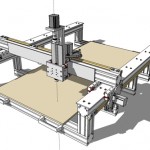
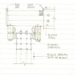
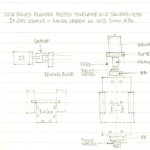
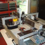
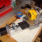
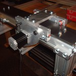
This subject apparatus is designed to remove material from wood, plastic, foam, soft metals and stone. It moves the cutting head and can affect pieces up to 50-inches long (x-a axis), 30-inches wide (y-axis) and 6-inches tall (z-axis). Due to its size, the X + Y axis are driven along a rack and pinion by 380-oz NEMA 23 steppers. The z-axis utilizes a 5-start screw drive to raise and lower the router assembly.
Material + Operation
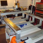
The table support is composed of 8020 aluminum extrusions with 1018 steel plate providing the carriage runways. A disposable MDF table surface serves as the clamping layer along with tracks on either side of the gantry. IGUS energy chains protect power and communication cables on the x-a and y axis. A dedicated computer runs the processing software converting stereolithography (STL) files into G-code, a numerical control programming language. This interface controls, among other things, cutting head position, elevation, spindle speed, rate of travel and cutting fluid application (metal only).
Power is provided through a 600-watt 120-volt supply to the four steppers. Instructions from the CPU interface with a Gecko 540 breakout board which includes an emergency shut-off circuit. Limit switches are installed to provide homing of the cutting head and prevent accidental over-travel.
A support stand (in development) will provide mounting and protection of the computer and the breakout board rack mount housing. It will also have casters allowing the machining to be moved within the shop.
